| Home | Energy Physics | Nuclear Power | Electricity | Climate Change | Lighting Control | Contacts | Links |
|---|
FNR FACILITY OVERVIEW:
This web page provides an overview of a practical urban sited 1000 MWt (300 MWe) Fast Neutron Reactor (FNR) Nuclear Power Plant (NPP). This facility includes the physical equipment necessary to safely supply electricity, high temperature industrial heat (450 degrees C steam) and low temperature district heat (warm water) to an urban market of up to 100,000 people. The NPP itself is designed to fit within one city block to minimize the amount of property that must be obtained by expropriation. Additional 20 m wide perimeter access ring roads are required.
The various related high voltage switchyard, transformers, local control rooms, human support services (cafeteria, lockers, offices, warehouse space, maintenance facilities and parking facilities should be located in nearby off-site space. The physical arrangement of these items is not critical, although it is helpful to be able to view relevant portions of the NPP and/orswitch yard from the corresponding local control rooms.
During NPP construction it may be necessary to occupy the equivalent of two spare blocks of nearby off-site space. Once NPP construction is complete it is sufficient to have the equivalent of only one additional block of nearby off-site space.
FNR FACILITY FOOTPRINT:
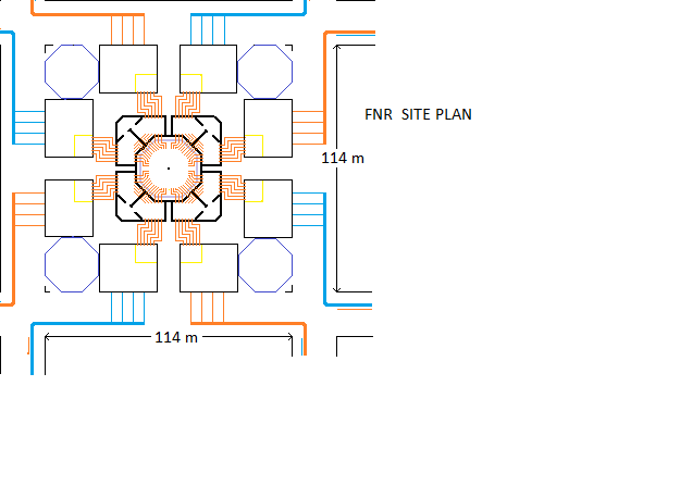
The minimum site real estate requirement is one square city block (114 m X 114 m). The perimeter road allowance width is 20 m. Then 12 city blocks have a length of:
12 (114 m + 20 m) = 1608 m
= 5275.6 feet.
There are 5280 feet / mile.
Usually the municipality requires a 7.5 m setback, so the above grade building space is limited to 99 m X 99 m.
The NPP consists of a 52 m diameter central nuclear island surrounded by eight steam turbogenerator barns with four small cooling towers located at the site corners. Argon silos, each 12 m in diameter, are mounted on top of the turbogenerator barns.
There are four 10 m wide X 23.5 m long radial lanes between pairs of turbogenerator barns. A flat deck truck, while delivering or removing a fuel bundle, will block one of these lanes. The turbogenerators should be oriented so that the generator portion faces the radial lane. Then the rotor pull allowance on both sides of the radial lane will provide space for lifting the turbogenerators and rotating them into place.
Most of the other FNR facilities such as argon cryosystems, electrical switch gear, etc. are located in, above or below the 8 turbogenerator barns. Each turbogenerator barn has outside dimensions of about 27 m X 13.5 m that must be shared by a 37.5 MWe turbo generator, condenser, injection water pumps, condenser cooling pumps and associated equipment. Issues of concern are the required dimensions for turbogenerator and condenser installation. Note that the district heating water circulation pumps are located at the thermal loads.
Note that the 48 inch diameter district heating loop headers are under the perimeter roads. The district heating branch pipes entering the turbogenerator barns are each 24 inch diameter. It is likely that the existing buried services under the perimeter roads will have to be rearranged.
Note that some main road allowances, instead of being 66 feet (20.11 m) are instead 86 feet (26.2 m) or 100 feet (30.48m). Such wider road allowances, if adjacent, will increase the total required property area.Heat moves from the heat exchange galleries located around the perimeter of the nuclear island to the turbogenerator barns via underground 8 inch 10 MPa steam pipes. Condensate moves from the turbogenerator barns back to the heat exchange galleries via 4 inch 10 MPa liquid water pipes.
The nuclear island contains a low pressure pool type liquid sodium cooled fast neutron reactor. Heat is transported via liquid NaK from heat exchange bundles immersed in the liquid sodium pool to heat exchange gallery mounted steam generators. There is sufficient on-site cooling tower capacity to reject fission product decay heat.
When the reactor is normally operating both off-site and on-site cooling towers connected to the buried low temperature district heating mains reject up to 700 MWt of heat.
A plan view of the physical plant is shown below.
AIR COOLING OF SERVICE SPACES INSIDE THE NUCLEAR ISLAND:
The nuclear island has a restricted service space between cool wall and the inner structural wall. Safe entry into the restricted service space is ambient radiation dependent and is generally prohibited while the reactor is operating at power. The NPP has unrestricted service space under the dome and between the inner and outer structural walls.
The Na pool, the thermal wall and the various pipes leak small amounts of heat into the restricted service space. This heat is transferred to the outside via conventional air conditioning fluid loops which keep the restricted service space airtight. The purpose of keeping the restricted service space airtight is to confine airborne radio isotopes in the event of a failure of both the nested hot and cool walls (the thermal wall).
A controlled air port connects the restricted service spaces to the outside. This port allows gradual air pressure balancing and air exchange while maintaining airborne radio isotope confinement.
APPEARANCE:
In plan view the footprint of an urban FNR physical plant is 99 m X 99 m and, allowing for legislated building setbacks, fully occupies one 114 m X 114 m city block. It is bounded by four public roads, each at least 20 m wide. Much of the below grade space under these public roads is occupied by 48 inch diameter district heating main headers and related 24 inch diameter branch pipe connections.
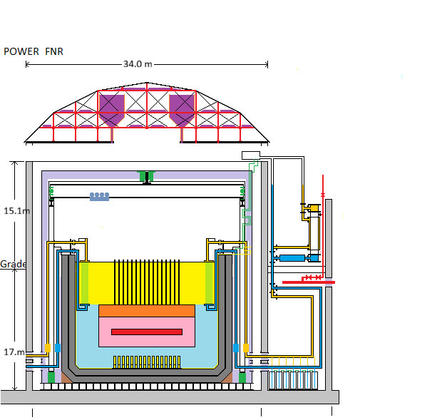
The FNR physical plant has a 52 m diameter central nuclear island, although its base plate may be as much as 54 m diameter. Centrally positioned, is a 34 m diameter inner structural wall that supports a 34 m diameter steel dome. There is 52 m OD, 50 m ID outer structural wall. The roof between the inner and outer structural walls consists of sloping panels that are removable to provide mobile crane access to the steam generators and induction pumps. The dimensions and specificaions of suitable mobile crane trucks are set out at: Crane Truck Features.
Spaced along the straight edges of the FNR physical plant site are 8 turbogenerator barns, each 13.5 m X 27 m. On top of the turbogenerator barns are 12 m diameter argon silos, each about 10 m tall.
At each corner of the FNR physical plant property is a 50 m high natural draft dry cooling tower that is 17.5 m wide at the base and about 50 m high.
The nuclear island is separated from the other on-site structures by a ring lane greater than 10 m wide. This lane is designed to accommodate mobile crane trucks with sufficient lifting capacity for installation and replacement of the steam generators and the induction pumps. The 10 MPa steam and condensate pipes pass underneath this ring lane. For chemical safety reasons there is no piped water connection into the space inside the inner structural wall.
There are 4 X 10 m wide radial lanes between the turbogenerator barns that provide direct flatbed truck access to the four nuclear island airlocks.
The ring and radial lanes are at grade level to allow easy movement of dollies bearing heavy loads such as 50 tonne steam generators.
The below grade district heating loop water pipes are integral to the reactor's heat rejection system. Each district heating loop connects to one local and three remote cooling towers. Each cooling tower is rated to dissipate at least 44 MWt on hot summerP>Note that the 48 inch diameter district heating loop headers are under the perimeter roads. The district heating pipes entering the turbogenerator halls are each 24 inch diameter. It is likely that the existing buried services under the perimeter roads will have to be rearranged.
There may be some tolerance in the turbogenerator hall dimensions depending on the exact equipment used.Note that a truck delivering or picking up a fuel bundle will have to back into a radial access lane. While lining up the truck with the access lane it will block the public road.
Note that some main road allowances, instead of being 66 feet (20.11 m) are instead 86 feet (26.2 m) or 100 feet (30.48m). Such wider road allowances, if adjacent, will increase the total required property area.
PHYSICAL PLANT:
The FNR physical plant includes the following essential elements:
1) The FNR sodium pool in a multi-nested wall reinforced concrete protective enclosure. The sodium pool maintains a top surface temperature of 460 to 500 degrees C;
2) Four heat exchange galleries spaced around the perimeter of the FNR sodium pool enclosure that transfer controllable amounts of heat from the FNR's negative pressure NaK loops to 10 MPa steam heat transport loops. The heat exchange galleries safely contain and suppress any NaK fire and provide supplementary physical protection for the FNR;
3) Eight siloed argon bladders that maintain one atmosphere of argon pressure inside the FNR enclosure, independent of the FNR temperature;
4) Four air locks located between the heat exchange galleries that enable replacement of: fuel bundles, intermediate heat exchange bundles and other equipment in the reactor space.
5) A 34 m diameter steel dome over the sodium pool which protects the sodium pool from both extreme weather and missile attack and which can contain airborne radio isotopes.
6) Four doors, under the airlocks, enable personnel access to the heat exchange galleries and dump tanks. Stairs on top of the airlocks probide access to the polar gantry crane and equipment mounted in the roof space under the dome.
7) Perimeter and radial laneways, each 10 m wide, enable delivery and removal of supplies, positioning of mobile cranes and short term vehicle parking;
8) Eight turbogenerator halls, that expand the steam through turbogenerators to produce electricity and condense the low pressure steam for district heating or heat rejection;
9) Four on-site cooling towers located at the site corners that together with twelve remote cooling towers are used for rejection of surplus low grade heat;
10) Four water reservoirs, located under the cooling towers, for emergency rejection of surplus heat by evaporation of water;
11) Electrical switchgear, protective devices and metering as necessary for interfacing the turbogenerators and parasitic loads with the external electricity grid, located in and above the turbogenerator barns;
12) Pipes and pumps, located below the turbogenerator barns, for interfacing with four district heating loops;
13) Below grade district heating loop isolation valves located under the property setbacks;
14) Control and monitoring systems that allow on-site or off-site personnel to view the status of all the operating equipment on FNR site, to selectively shut down and restart individual components and to communicate planned maintenance related information for power and maintenance dispatch.
15) Redundant cryogenic facilities for on-site liquid argon production and potential capture of radioactive inert gases.
16) Dual emergency power generators. At all times when the FNR sodium is above 120 degrees C there must be sufficient emergency power available to remove fission product decay heat from the sodium pool by circulation of NaK and then evaporation of water.
ELECTRICAL:
Each of the eight turbogenerators operates independently of all the others. There is a split station bus. The external electrical grid connect breaker goes to a common point which connects to breakers to each half of the station bus, breakers to each of two standby generators and two breakers to the two independent shutdown systems of the nuclear island. This common point is always energized except after a prolonged reactor shutdown.
Each half of the station bus contains four breakers to turbogenerator outputs, and four breakers to the associated non-nuclear parasitic loads.
Thus either one of the emergency generators can be used to start any one of the turbogenerators, then power from that turbogenerator can be used to start the remaining turbogenerators. At any stage during this process the station bus can be connected to the external electrical grid.
During normal operation any combination of turbogenerators can be taken out of service for maintenance provided that at least two turbogenerators remain in service to meet the station parasitic load if there is an external grid failure.
If there is loss of the external grid the two standby generators should be started so that the station bus remains powered if something causes shutdown of the operating turbogenerators.
ELECTRICAL EQUIPMENT LOCATION:
The electrical switchgear associated with each electricity generator is located in the relevant turbogenerator barn. If a major transformer is required to interface the station bus voltage to the grid voltage that transformer may have to be located off-site.
HUMAN AND OTHER SUPPORT SERVICES:
Due to limited space on the NPP site the control rooms, human support and maintenance services are located in nearby buildings across the road or otherwise as close as practical to the NPP site. The space required for these support services is much larger during the construction period than during the subsequent operating period. At times when the FNR is shut down for major maintenance additional human support facilities may again be required.
The human support facilities include:
1) The control rooms for the nuclear island.
2) Control rooms for the turbogenerator and district heating equipment. This equipment is divided into four independent portions, each portion serving a different quadrent of the surrounding district heating system. In effect there are four independent 75 MWe power plants sharing the same common FNR sodium pool.
3) Washrooms;
4) Office space for employees and subcontractors;
5) Storage space for frequently required files, tools, supplies and spare parts.
6) A larger space suitable for on-site meetings and visitor presentations.
7) Cafeteria space;
8) Site security space;
9) Employee and visitor parking space;
10) Flat deck truck and mobile crane parking space;
11) Construction material storage space;
12) Parking space for contractor trailers, subcontractor vehicles, etc.
FNR ENCLOSURE:
The sodium pool is a 20 m diameter pool of liquid sodium with a top surface temperature of about 460 to 500 degrees C. This pool is centrally located within a 26 m diameter cylindrical enclosure. The inner structural wall is 1 m thick reinforced concrete 34 m OD, 32 m ID. There is a metal sheathed thermal wall 26 m ID, 29.6 m OD containing fiber ceramic thermal insulation. The thermal wall and the inner xtructural wall absorb gamma ray emissions and completely exclude air and water from the sodium.
The concrete wall inner structural wall is stabilized on the outside by 8 X 1 m thick reinforced concrete shear walls, and 44 minor shear walls, each minor shear wall extending radially 8 m from 13 m below grade to 1 m below grade. The 8 major shear walls form the end walls of the heat exchange galleries.
The FNR sodium pool is further protected from low angle aircraft impact by the 1 m thick concrete outer structural wall of the heat exchange galleries, by the ring of steam generators and induction pumps contained in the heat exchange galleries.
The FNR sodium pool is protected from overhead attack by a concrete roof and structural steel dome which rises about 8.5 m above the top of the inner structural wall.
SITE PLAN DESCRIPTION:
On the site plan the blue octagons at the site corners are cooling towers built over buried water tanks. The black rectangles around the site perimeter are turbogenerator barns each of which contains one 37.5 MWe turbogenerator and associated condenser, and six injection water pumps. Significant amounts of below grade space in the turbogenerator halls must be reserved for the condenser, district heating water pipes and appropriate service clearances.
Electrical switchgear is located in or above the turbogenerator barns.
ARGON BLADDERS:
The liquid sodium pool cover gas is an inert gas argon which will not chemically react with either the liquid sodium or steel. The argon pressure is maintained at one atmosphere by argon filled bladders that are surrounded by air at atmospheric pressure. As the argon over the sodium pool expands argon flows into the bladders via gas coolers. This simple argon pressure control system does not require AC power. Fail safe argon space pressure control is essential for FNR enclosure structural integrity.
HEAT EXCHANGE GALLERIES:
Outside the inner structural wall are the four heat exchange galleries that extend 9.0 m out from the inner structural wall. The heat exchange gallery end walls double as 1 m thick shear walls and serve the secondary function of protecting the sodium pool from low angle airplane or artillary attack. The outside diameter of the central nuclear island building is:
52 m.
The purpose of the heat exchange galleries is to safely transfer controllable amounts of heat from negative gauge pressure NaK to water/steam.
The inside width of each heat exchange gallery is 8.0 m. Each heat exchange gallery contains 12 steam generators and 12 induction pumps.
The 10 MPa steam pipes and condensate return pipes are routed under the 10 m wide laneway to the turbogenerators. The diagram below shows the piping for one of 48 identical heat transfer circuits.
The steam generator manifold end covers are removeable for service access and for interior welding inspection, so these end covers are free of pipe connections.
The high points or each NaK circuit are connected to a vacuum tank that is over pressure vented to the atmosphere via a rupture disk and ball check. Under accident conditions this vent can discharge hot steam and hydrogen while trapping NaK. The volume of this vacuum tank must be sufficient for NaK trapping.
The vents are designed to prevent NaK hammer damage that might otherwise occur on the rupture of a steam generator heat exchange tube.
There is a 16 inch OD schedule 40 pipe that conveys NaK from each intermediate heat exchange bundle to the jacket bottom connection of the corresponding steam generator.
Directly under this pipe is the corresponding induction pump. It pumps cooler NaK from the bottom manifold of the steam generator back toward the intermediate heat exchanger. There is provision for expulsion of liquid NaK from the companion intermediate heat exchange bundle. At each NaK circuit low point there is a tee. The tee branch goes down to the NaK dump tank.
The purpose of the dump tanks is to lower the NaK level below the level of the steam generator and induction pump in the event of a steam generator tube leak.
This NaK level lowering is achieved by releasing the argon charge over the NaK dump tank to the corresponding vacuum tank.
Ideally the steam generator should be located high enough above the top surface of the sodium pool to ensure that fission product decay heat can be safely extracted by natural circulation of NaK.
The equipment in the heat exchange galleries is supported by ~ 10 m long horizontal I beams that are embedded in the structural walls.
Just aqbove the baseplate are dump tanks into which the NaK can be transfered for NaK fire suppression or to permit equipment or pipe service.
FIRE PREVENTION:
The main means of sodium fire extinguishing is oxygen exclusion and argon cover to keep the sodium isolated from air. If there is a NaK fire it will be the result of NaK leaking out of a NaK circuit. The immediate remedy is to release argon pressure from over appropriate NaK dump tank and let gravity transfer that circuit's NaK into its dump tank. This transfer will asphyxiate a NaK fire very quickly.
Floating on top of the liquid sodium pool are spherical steel floats that reduce the exposed liquid sodium surface area. These floats are sized to permit the vertical indicator tubes to show the movable active fuel bundle status. The upper manifolds of the intermediate heat exchange bundles also cover part of the top surface of the liquid sodium.
When the reactor is completely shut down, before the sodium argon cover gas removed, the sodium surface should be flooded with kerosene to prevent oxidation. However, in the presence of air (oxygen) that kerosene is a potential fire hazard. The number one objective is to keep oxygen out of the enclosed sodium pool space. Any oxygen or water vapor that leaks in will likely eventually form Na2O or NaOH which must be filtered out of the sodium.
ROOF FUNCTIONS:
The main function of the FNR's dome roof structure is to exclude air and provide physical protection against precipitation, violent storms (hurricanes and tornados), long term corrosion and missle attack. The roof structure must also house forced air cooling equipment, and provide structural support for the thermal ceiling and electronic monitoring system.
The hot wall provides structural support for the polar gantry crane.
The hot and cool surfaces of the thermal wall and thermal ceiling contain fiberfrax insulation and argon gas and exclude air. The stainless steel cool ceiling covering also provides secondary protection against a dome rain water leak.
The hot ceiling surface must be 10 m above the pool deck to allow fuel bundle and intermediate heat exchange bundle repositioning and replacement using the internal polar gantry crane. The sodium pool enclosure hot wall, cool wall and inner structural wall amust be all be gas tight and must dependably exclude both air and rain water under the most adverse circumstances.
Between the steel roof structure and the cool ceiling upper surface is a ___ m high space that allows easy access to the ceiling mounted reactor monitoring system, air cooling equipment and NaK loop vacuum tanks.
GANTRY CRANE:
The gantry crane must work reliably after being in the ~ 500 degree C sodium vapor environment for an extended period of time. Temperature sensitive components must be removed to cool storage when the gantry crane is not in use.
The detail of the connection methodology between the gantry crane remote manipulator and the gantry crane trolley remains to be resolved. Also the detail of how to power the gantry crane remote manipulator needs to be resolved (Will teflon insulated cable work?). This remote manipulator must be able to precisely place fuel bundles and reliably connect and disconnect fixed fuel bundle corners together 6 m below the liquid sodium surface.
DEFENSE AGAINST A POTENTIAL AERIAL ATTACK:
The FNR dome must be strong enough to safely absorb an aircraft crash. It will likely have a structual steel content comparable to a major highway intersection overpass. The dome contains horizontal layers of sand bags under its floor sufficient to provide safety shielding from Na-24 radiatin emitted by the sodium surface.
If an imminent threat to the FNR from an air born object is detected the FNR should be immediately cool shut down. To the extent that time permits sufficient heat should be extracted from the liquid sodium pool to prevent spontaneous combustion of sodium with air if there is a major enclosure failure.
If at any time air leaks into the argon cover gas the immediate requirement is to rapidly lower the liquid sodium temperature below 200 C to prevent spontaneous sodium combustion.
The overhead steel dome, the strong concrete and steel structure of the heat exchange galleries located around the FNR enclosure perimeter and
the related shear walls make the FNR enclosure very resistant to airborne physical attack. Within a few seconds the liquid NaK in the heat exchange galleries can be drained down to argon covered dump tanks to rapidly extinguish almost any NaK fire.
FNR DOME:
The sodium pool enclosure dome shaped roof is formed from structural steel. The dome design is constrained by the use of prefabricated structural steel beams that are length limited by road and rail transportation constraints to 15.8 m.
Designing a roof that can withstand a deliberate direct overhead attack by a precision guided armour penetrating bomb is almost impossible. If such attacks are a credible risk it may ultimately be necessary to locate FNRs deep underground to provide certain security against such intentional overhead military attacks.
A reasonable compromise is to locate the liquid sodium pool for the new FNR such that in an emergency a NaCl crust and an argon gas cover can be maintained over the liquid sodium pool while a temporary new roof is applied. The FNR dome roof should have a constant curvature to permit quick patching. In such circumstances the liquid sodium pool should be cooled below 140 degrees C and then covered with a kerosene to prevent sodium combustion with air. Circumstances that might lead to such a roof failure include a direct overhead impact by an armour penetrating bomb, missle or meteorite.
There should be a sufficiently large supply of on-site stored argon to prevent sodium combustion while the liquid sodium temperature is being reduced following a sudden roof failure.
There should be preformed sheets of curved roof patching material stored on-site together with appropriate tools and supplies sufficient for temporary blocking of any hole in the roof caused by a penetrating missle. In order to execute this fix the gamma radiation in the roof space from Na-24 in the sodium pool must be quantified. There must be a shielded route for safely accessing the reactor monitoring system and roof space mounted ventilation equipment.
The dome interior space should have a liquid tight sloped floor that will guide any released liquid aircraft fuel to a steel pipe drain. That drain must go to a sewage dump tank that is nearly sealed.
A 300 MWe FNR has 8 fully independent heat removal systems connected to four independent cooling towers. This level of independence provides protection in depth against a loss of cooling failure.
SAFE ACCESS TO ROOF SPACE:
In the absence of sufficient over ceiling shielding unrestricted safe access to the inside of the dome is only available after the reactor has been shut down for a week so that the gamma emission from Na-24 is low. Hence provision should be made for safe servicing of the ceiling mounted electronics packages.
This may involve a shielded route via the stairwells and a shielded cat walk and/or work cart. The worst case level of Na-24 gamma radiation in the ceiling space needs to be identified.
NON-NUCLEAR MAINTENANCE:
On-site personnel are required to do periodic routine non-nuclear preventive maintenance on the induction pumps, steam generators and steam pressure regulating valves in the heat exchange galleries. These galleries are radiation shielded.
There is also required maintenance on drain valves, water pumps, turbo-generators, condensers, cooling towers and related mechanical and electrical equipment in the surrounding turbogenerator barns. However, this maintenance work should not involve any potential exposure to dangerous radiation. There is sufficient redundancy in the intermediate heat exchangers that some of the heat transport systems can be shut down for later skilled maintenance or repair while other heat transport systems remain in operation. Thus the only reason for keeping staff on the FNR site 24/7 is compliance with steam power plant regulations and site security.
FISSION PRODUCT DECAY HEAT REMOVAL:
One of the most important aspects of fission reactor design is provision for fission product decay heat removal under adverse circumstances. If some event occurs which causes a reactor shutdown the fission products will continue to produce decay heat at up to 8% of the reactor's full power rating. It is essential to have a 100% reliable means of ensuring ongoing removal of the fission product decay heat under adverse conditions such as shortly after a severe earthquake when there may be no externally suppled AC power or after a roof failure due to a military armour piercing bomb or jihadi attack.
There must be certainty about removal of this heat. A FNR has multiple independent heat transport systems, proper operation of 8% of which is sufficient for fission product decay heat removal. In the event of loss of station power fission product decay heat removal should be achieved by natural NaK circulation.
If there is a house power failure the sodium will warmup causing a fission shutdown. Removal of fission product decay heat will still require NaK circulation. Shut down all but two genertors. The fision product decay heat should initially keep these two turbogenerators operataing. The electrical load will be house power.
During normal reactor operation for safety certainty at any instant in time at least 2 of the 8 turbogeneratorss with 2 different cooling towers should be kept operational.
For a liquid sodium cooled FNR all heat removal is via liquid sodium and NaK, so it is essential that:
1) Under no circumstances will the liquid sodium level ever fall to the point that the fuel rods are not fully immersed in liquid sodium.
2) The intermediate heat exchange tubes must always be at least partially immersed in liquid sodium.
3) The liquid sodium pool walls are designed such that if the inner and middle nested steel cup walls fail and the liquid sodium leaks into the space between the walls, the sodium leakage into the space between the walls will not lower the liquid sodium level below the tops of the fuel tubes.
3) If the NaK induction pumps fail there must be enough natural NaK circulation to ensure safe removal of the fission product decay heat.
4) The NaK dumps its heat into steam generators. During a reactor cold shutdown NaK is used to remove heat until the Na approaches its freezing point.
5) There must be enough clean water in on-site storage such that in an emergency the fission product decay heat can be removed by evaporation of water.
CHEMICAL THREATS:
The main chemical threat from a power FNR is the 3770 m^3 of liquid sodium contained in the sodium pool. If this liquid sodium contacts water there will be an explosive chemical reaction which liberates hydrogen that will spontaneously ignite in an air atmosphere. Hence one of the main issues in FNR application is choice of a reactor site where the sodium will NEVER be exposed to flood water.
Even if the reactor enclosure floods 14 m deep the outer stainless steel wall around the sodium pool should prevent any contact between water and the primary sodium.
The other main potential threat is a sodium fire. Quite apart from the release of Na-24, Na2O and NaOH the big threat from a prolonged fire is melting of the fuel tubes leading to potential release of air borne plutonium and fission products. It is essential that the reactor be designed and sited such that a large sustained primary sodium fire cannot occur. In order to extinguish a sodium fire the oxygen concentration over the sodium must be minimized and heat must be extracted from the sodium. Under no circumstances can water be allowed to contact the primary sodium.
The soil and bedrock outside the concrete enclosure should be sufficiently dry, dense and stable to safely contain the liquid sodium in the unlikely event that a major earthquake ruptures the inner, middle and outer steel cup walls of the liquid sodium pool and cracks the enclosing concrete wall.
It is equally important that there be an effective non-water based fire suppression system. The local fire department must be trained that water should NEVER be used to fight a FNR fire. Inappropriate use of water carried by a fire truck could change a minor fire into a major disaster. The FNR is provided with excess argon and NaCl in silo storage for emergency use. The default means of stopping a NaK fire is NaK drain down into a dump tank. In each heat exchange gallery this drain down mechanism should be automatic. However, in no circumstance can all the heat transport capacity be taken out of service.
To mitigate the fire threat the liquid sodium pool surface is covered by floating steel balls, an argon cover atmosphere, a sodium vapor resistant and gas tight inner metal ceiling, and a gas tight middle and outer metal ceilings. In the event of air penetration into the argon cover gas the reactor should be immediately shut down and heat dumped from the liquid sodium pool to lower the liquid sodium temperature below 200 degrees C so as to prevent spantaneous combustion of sodium in air. As the argon temperature over the sodium pool decreases stored argon from bladders in the argon storage silos is added to the cover gas to maintain the 1 atmosphere pressure in the argon cover gas. Note that there is a small air leak between the bladder surround space and the outside.
Once the liquid sodium temperature is below 140 degrees C the surface of the liquid sodium can be flooded with a thin layer of kerosene to prevent the liquid sodium oxidizing during prolonged work such as roof repair.
Similarly if there is an enclosure roof failure the immediate objective is to extract heat from the liquid sodium to reduce its temperature to the point where kerosene can be safely used to prevent sodium oxidation. Until the heat is removed from the sodium argon must be used to exclude oxygen from the sodium surface. That heat extraction might easily take half an hour.
It is important to have enough water in on-site tank storage to remove the fission product decay heat by latent heat of vaporization. Then the limiting factor is the maximum safe heat transfer capacity of the heat transport system. If there is a FNR roof failure it is essential to use dry cooling to prevent vented steam condensing and falling onto the exposed liquid sodium surface. This issue highlights the importance of FNR enclosure roof and ceiling integrity and immediate availability of roof repair material for temporary exclusion of rain or other water falling from overhead.
RESERVE STORAGE FOR FUEL BUNDLES AND SODIUM:
Eventually it may be necessary to do maintenance work on the sodium pool inner wall. To do such work it will be necessary to remove all the fuel bundles and the liquid sodium from the sodium pool. Hence there must be nearby sodium storage with sufficient capacity to hold the entire volume of the liquid sodium while the aforementioned maintenance work is being carried out. Ideally the reserve sodium storage might must also be able to accept hot active fuel bundles transferred from the liquid sodium pool. The best place to store these hot fuel bundles is in another nearby liquid sodium cooled reactor. The fuel bundle transport truck may need special provisions for fuel bundle cooling while driving.
COOLING TOWERS:
During the winter much of the reactor waste heat output from electricity generation is dumped to a water based district heating system. In the summer the highest temperature of this district heating water is about 80 degrees C. Generally there is a heat pump in every building to raise the temperature of the building heating water during the winter.
If the district heating load is smaller than the waste heat from electricity generation the surplus heat is rejected via distributed cooling towers.
However, in the event of a loss of power at the reactor location the circulation pumps of the district heating system may not operate. In these circumstances the reactor must be able to reject fission product decay heat at the reactor location using just two of its four on-site cooling towers.
Note that the 48 inch diameter district heating loop headers are under the perimeter roads. The district heating pipes entering the turbogenerator halls are each 24 inch diameter. It is likely that the existing buried services under the perimeter roads will have to be rearranged.
There may be some tolerance in the turbogenerator hall dimensions depending on the exact equipment used.Note that some main road allowances, instead of being 66 feet (20.11 m) are instead 86 feet (26.2 m) or 100 feet (30.48m). Such wider road allowances, if adjacent, will increase the total required property area.
EMERGENCY COOLING:
In an emergency cooling towers can be operated wet. The resulting steam plume may not thrill the neighbours, but it is far better than a thermal meltdown resulting from inability to safely reject fission product decay heat.
At the reactor site there are four independent natural draft cooling towers. Each such cooling tower is sized and piped to safely reject at least half of the maximu fission product decay heat. Assuming that all cooling towers remain in service the additional heat rejection capacity will enable system black start which will include energizing the district heating system circulating pumps and the remote cooling tower pumps. Once there is remote heat rejection capacity the reactor power can be increased.
The minimum required continuous cooling capacity is:
700 MWt / 16 cooling towers = 43.75 MWt / tower.
Each remote cooling tower should be installed on a 40 m X 40 m remote property so as to provide a 7.5 m setback from the property line to the 25 m diameter base of the cooling tower. These cooling towers should be spaced along and close to the district heating main distribution pipe routes. Typically the cooling tower sites must be obtained by purchase/expropriation of two adjacent 20 m X 40 m residential properties.
WATER RESERVIORS
It is prudent to have on the reactor site a certain source of water sufficient to remove fission product decay heat by evaporation in emergency circumstances when the normal heat sink capacity is unavailable. The reserve water storage reservoirs can be located underneath each cooling tower.
Assume that emergency cooling water is stored in four on-site below grade cylindrical tanks, each 20 m high by 15.5 m inside diameter, located directly below the cooling towers. Then the volume of water immediately available on-site for emergency cooling is:
4 X Pi (15.5 m / 2)^2 X 20 m
= 15,095 m^3
= 15.095 X10^6 kg
The latent heat of vaporization of water is:
22.6 X 10^5 J / kg
Hence evaporation of this stored water requires:
22.6 X 10^5 J / kg X 15.095 X 10^6 kg
= 341.15 X 10^11 J
Without any use of the dry cooling tower capacity that amount of water is sufficient to remove maximum fission product decay heat of:
0.08 X 1000 MWt = 80 MWt for:
341.15 X 10^11 J / (80 X 10^6 J / s)
= 4.264 X 10^5 s
= 4.264 X 10^5 s / (3600 s / h)
= 118 hours.
That is sufficient for disposing of fission product decay heat.
During the course of this disaster situation it is necessary to lift:
15.095 X 10^6 kg water / 118 hours = 127.9 tonnes / hour of water from the storage location to the top of the steam generators. That requires absolutely reliable standby power generation. The required pumping power is:
127.9 X 10^3 kg X 30 m X 9.8 m / s^2 X 1 / 3600 s
= (127.9 X 30 X 9.8) / 3.6 kg m^2 / s^3
= 10,445 (kg m^2 / s^2) / s
= 10,445 J / s
= 10.445 kW
Allowing for motor and pump inefficiencies redundant 25 kW pumps are required.
This web page last updated February 26, 2026
| Home | Energy Physics | Nuclear Power | Electricity | Climate Change | Lighting Control | Contacts | Links |
|---|